The transformer is a basic voltage control device that is widely used in AC power distribution and transmission.
The idea of the transformer was first introduced by Michael Faraday in 1831 and was continued by many other prominent scientists. However, the general purpose of using a transformer today is to control and output varying levels of voltages (either up or down) while maintaining the balance and frequency of current.
How Do Transformers Work?
Electrical transformers use Faraday’s law of electromagnetic induction to operate which says:
“The rate of change of the flux relationship with respect to time is directly proportional to the EMF induced in the wire or coil.”
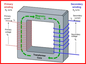
The physical basis of the transformer lies in the mutual induction between two circuits connected by a common magnetic flux usually equipped with 2 windings: primary and secondary. These coils share a laminated magnetic core, and the mutual induction that occurs between these circuits helps carry electricity from one point to another.
Design and Parts

The three important components of an electric transformer are the magnetic core, the primary winding, and the secondary winding. (shown above)
The primary coil is the part connected to the mains from which the magnetic flux is initially generated. These coils are isolated from each other and the primary flux is induced in the primary winding, from where it is transferred to the magnetic core. This is then connected to the secondary winding of the transformer via a low-impedance line.
The core passes flux to the secondary winding to create a magnetic circuit that shuts down the flux. This in turn brings a low resistance path in the core to maximize flux coupling. The secondary winding helps to complete the flux movement which starts from the primary side and reaches the secondary winding with the help of the core.
In all types of transformers, the magnetic core is assembled by stacking layered steel sheets, leaving the minimum necessary air gap between them to ensure the continuity of the magnetic path.
Uses and Applications
- To Increase or decrease the voltage level in an AC circuit.
- It increases or decreases the value of an inductor or capacitor in an AC circuit.
- It prevents direct current from flowing from one circuit to another.
- It increases the voltage level at the power generation site before transmission and distribution can take place.
Transformers are often used in electrical applications where voltage control is needed to power more than one circuit of varying voltages. much larger units can be found in pumping stations, railroads, industrial and commercial establishments, windmills, and power generation units, etc. to name a few.
PDFs / Technicals
Types Of Transformers
Electrical transformers can be divided into different categories based on their designs, purpose, delivery, and intended use.
Based On Design

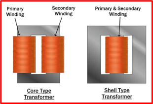
- Core-Type Transformers
This transformer has two horizontal sections with two vertical legs and a rectangular core with a series of magnets. The two cylindrical coils (HV and LV) are placed at the center end of the transformer core.
- Shell-Type Transformers
The shell-type transformer has dual magnetic circuits and a center end with two outer ends.
Based On Supply/Delivery

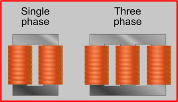
- Single-Phase Transformer
A single-phase transformer has only one circuit of windings. Generally, single-phase transformers are used in low-voltage appliances like home appliances.
- Three-Phase Transformer
A three-phase (or 3-phase) transformer has three sets of primary and secondary windings to form a group of three single-phase transformers. Three-phase transformers are mainly used for power generation, transmission, and distribution in the industry.
Based On Purpose

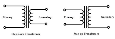
- Step-Up Transformer
This type is determined by the number of wire turns. So,if the number of secondary windings is more than that of the primary windings, it means that the voltage is the same and that forms the basis of the step-up transformer.
- Step-Down Transformer
This type is usually used to lower the voltage level in the electricity transmission and distribution network. The mechanism being used in step-down transformers is the opposite of step-up transformers.
Based On Usage
- Power Transformer
Power transformers are usually used to transmit electricity and they have high power ratings.
- Distribution Transformer
These transformers have a relatively lower capacity and are used to distribute electricity.
- Instrument Transformer
This transformer is further divided into Current transformer and Potential transformer.
Current and Potential transformers are used for instrument relay and protection at the same time.
Useful Resources
Wire Connectors: Sizes, Types, and Charts
Circuit Breaker Basics: Testing, Types and Ratings
How To Test A Motor With A Megohmmeter
Fluorescent Ballasts: What They Do and How
Electrical Resistance: How It Works