What Is A Motor Starter?
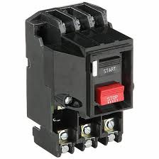
A Motor starter is an electromechanical switch similar to that of a relay, whose main function is to start and stop the motor to which it is attached to.
A starter is essentially a switching mechanism made up of electrical contacts (both incoming and outgoing). Starters are classified into hand-operated and electrically-operated.
The side of a hand-operated starter has a lever that can be used to switch it on or off. These are typically used for smaller motors because they cannot be operated remotely. The motors are restarted instantly following a power outage due to this type of motor starter.
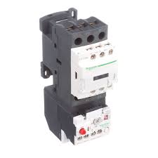
The motor could be damaged as a result of the motor operating immediately after a power outage and allowing potentially dangerous current to flow into it. Because of this, most starters come with electrical switches.
The spring arrangement pulls contacts back to their original positions when the coil is de-energized. To energize and de-energize the coil and activate the contacts, motor starters are typically equipped with push buttons (designated as start and stop buttons).
These electrically powered starters need to be “started” to restart after a power outage.
PDFs / Technicals
Introduction: Types of Motor Starters
ABB: Motor Protection and Control
Motor Starting Methods
Three-phase induction-type motors are typically used in industrial operations most of the time compared to any other form of motor. An induction motor with three phases can be started using a variety of methods:
- Full Voltage Method
In this method, the motor is a self-starting one by nature and needs full voltage to start, full voltage (or rated voltage) is placed across it in this manner. Motors with a rating of less than 5 HP typically use this method.
- Reduced Voltage Method
This method is commonly used with large motors rated at 100 HP and above (or for a motor that requires very high starting current). These high-rated motors demand extremely large starting current and may also result in a voltage drop in the line.

In such situations, a reduced voltage technique is utilized, in which the motor’s voltage is first applied at a lower level for a short time to start the motor rotating, and then the voltage is raised to the rated supply voltage to cause the motor to rotate at the specified speed.
- Bidirectional Method
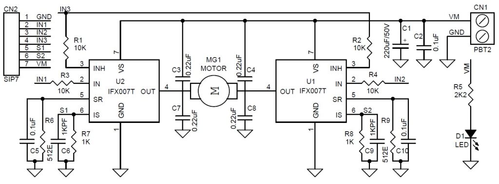
In this technique, two or more contactors are used, and they are connected and interlocked in a suitable way to allow for bidirectional functioning.
- Multi-Speed Method
With this technique, motor starters are designed to supply various voltages to the motor at various speeds. These starters are typically made to run the motor at least twice—often twice—and three times—using contactors.
Types Of Motor Starters
- Stator Resistance Starter
This technique involves interconnecting external resistances in series with each phase of the stator winding to lower the voltage provided to the induction motor.
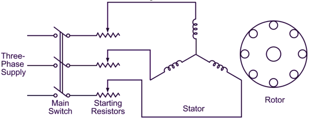
These resistances are maintained in their maximum position during motor starting, resulting in a lower voltage applied across the motor due to a significant voltage drop across the resistances.
The resistance associated with each phase in the stator circuit gradually decreases as the motor gains speed. The motor receives a rated voltage (full voltage) when these resistances are removed from the circuit, which causes it to run at the rated speed.
- Star-Delta Starter
The induction motor is linked in star during start-up and delta while operating at rated speeds.
These starters are made to function with an induction motor’s stator that is connected in a delta configuration.
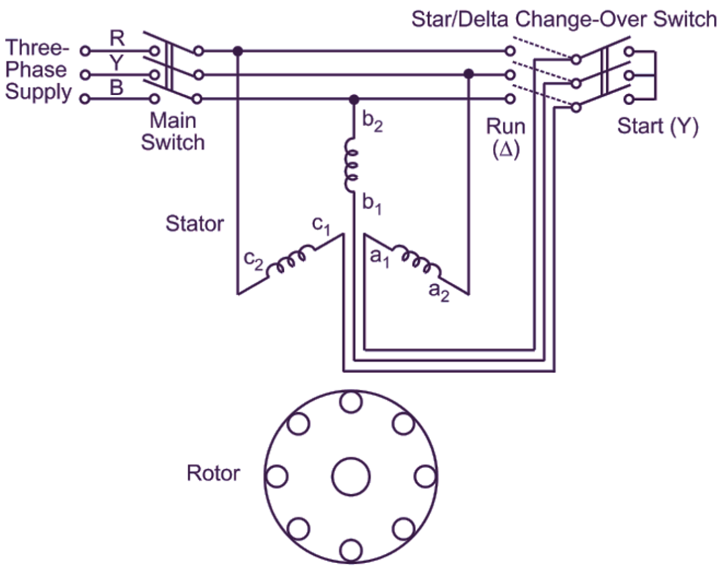
During the starting condition, this starter links the stator winding in the starter using a TPDT (Triple Pole Double Throw) switch. This star connection causes a reduction in applied voltage to the motor of 1/3 as a result. Because of the lower voltage, the motor receives less current.
By employing relays, the TPST switch is automatically thrown on the opposite side when the motor accelerates, resulting in the winding being connected in delta across the supply. Hence the starter operates at normal speed.
- Direct On-line Starter
Small-capacity motors (those with less than 5 HP) don’t require a starter because the starting current isnt very high.
Since there is no need to lower the motor’s starting voltage, the motor can be connected straight to the supply lines. The direct online starter is the name given to this type of starter configuration.
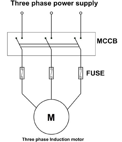
The magnetizing coil is ignited during the start condition when the normally open contact is pushed for a brief time. The coil’s magnetic flux draws the contactor, connecting the motor to the supply as a result.
The contactor stays in this position as the extra switch supplies power to the coil. By de-energizing the coil and separating the contactor with a spring arrangement when a usually closed switch is depressed, the supply to the motor is cut off.
Any overload condition results in a significant current draw from the motor, which raises its temperature. Overload sensors are used to control the thermal relays during this severe heating. Then, overload contacts work to cut off the supply to the motor.
- Soft Starter
The starting voltage and current supplied to the induction motor by the soft starter are controlled by semiconductor switches like thyristors.
Variable voltage is provided by a phase-controlled thyristor. By changing the conduction angle or firing angle of the thyristors, the voltage can be changed. To give lower voltage, the conduction angle is kept to a minimum.
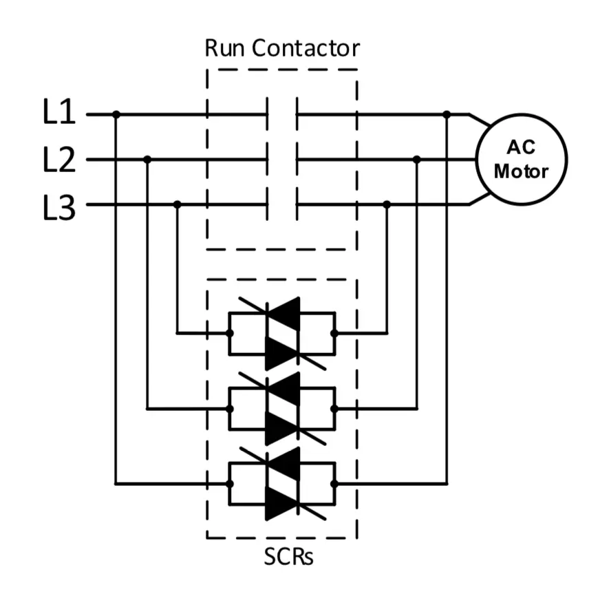
By raising the conduction angle, the voltage is steadily increased. The induction motor receives full line voltage and operates at rated speed when the conduction angle is at its maximum. The beginning voltage, current, and torque grow gradually and smoothly as a result.
Useful Resources
Continued learning..
Dimmer Switches: Wiring, Diagrams and Installation Suggestions
Phase Monitoring Relays: How They Work
Voltage Drop Calculator and Formulas Explained