How To Test A Capacitor
Capacitors are used in the storage of electricity. In contrast to the usefulness of resistors, capacitors do not dissipate energy in their optimal form.
However, in actual operation, capacitors lose a little amount of energy. The dielectric will be enveloped by an electric field when a voltage (electric potential difference) is applied across the capacitor’s terminals.
This procedure permits the capacitor to accumulate a net negative charge on one plate and the negative form on the other.
Charge flows via the capacitor’s source circuit, but no current flows through the dielectric.
How To Test The Effectiveness Of A Capacitor
During maintenance or troubleshooting, capacitors must be examined and tested. To test a capacitor, below are the different ways to test for a capacitor:
- Using an AC Supply
- By using the Ohmmeter Setting Mode of a Multimeter
- By Using the Capacitance Setting Mode of a Multimeter
- By using a Voltmeter
Using An AC Supply
Only experienced electrical experts should use this method because it is so risky. Using 24V DC or 220-224V AC rather than 230V AC for this procedure is safer.
When using 220-224V AC, series resistors must be connected between the capacitor.
The procedure for this method is as follows:
- The capacitor to be tested must be fully disconnected or the suspected capacitor should have at least one lead disconnected.
- The capacitor should be fully discharged. Then the capacitor’s terminal should receive the leads, these leads should then be briefly (1–4 seconds) linked to a 230V AC supply. Now take the leads out of the supply.
- After taking the lead out of the supply, the next step which is the crucial and riskiest step is to shorten the capacitor’s terminal. After this process, it will be observed that a significant spark will be generated if the capacitor is functioning properly and if it is not, a weak spark is created. This shows that the capacitor is not in good condition.
Testing A Capacitor With A Multimeter

Using The Ohmmeter Setting Mode Of A Multimeter
If you don’t have one, the Fluke 117/323 Kit is probably the best bang for your buck
The step-by-step method for this technique is as follows:
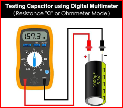
- The capacitor to be tested must be fully discharged. Then the ohmmeter setting on the multimeter should be used.
- Connect the meter’s leads to the capacitor’s terminals as show above.
It is important to take note of the reading and compare the outcome with the information below:
- The low resistance value suggests that the capacitor is short.
- If there is no deflection in the meter, the capacitor is open.
- When the resistance on the meter starts low and then gradually grows to infinite, that indicates a good capacitor.
Using The Capacitance Settings Mode Of A Multimeter
The capacitor can be checked using this straightforward and effective technique.
- As usual, the capacitor that will be tested needs to be discharged. Then the capacitance setting on the multimeter must be selected.
- Now, join the meter’s leads to the capacitor’s terminals. Polarity is not an issue in this situation. The capacitance value that is almost close to the suspected capacitor’s capacitance rating is displayed in the meter.
- A decreased capacitance reading or no values at all in the meter indicates a faulty capacitor.
By Using A Voltmeter
The capacitor’s potential difference is determined using this technique. The process is outlined below;
- First, a DC voltage that is below the rating of the capacitor is used to charge the capacitor.
- The capacitor’s shorter lead (cathode) is linked to the ground or negative voltage terminal, and the capacitor’s longer lead (anode) is connected to a positive voltage. It is recommended to connect the voltmeter’s terminals across the capacitor’s terminals.
- The capacitor is in good shape if it reads the same voltage as when we charged it and then starts to fall. The capacitor is not good or in poor condition, if it is not charging when the voltmeter displays a reading.
The above steps are used in determining the condition and effectiveness of a capacitor.
A capacitor is a simple storage device used to store electrical charges and release them when the circuit requires them. Many different duties, including smoothing, filtering, bypassing, etc., are carried out by capacitors in electrical circuits. It is possible that not every application requires a certain kind of capacitor.
Useful Resources
Continued Learning:
Fault Interrupters: AFCI vs GFCI
The Difference Between an Alternator vs Generator
Troubleshooting Rectifiers: Intro to Circuits and Diodes
Step up and Step Down Transformers
FAQs
How do capacitors work?
Capacitors are used to store electricity. In contrast to the usefulness of resistors, capacitors do not dissipate energy in their optimal form. Read more..
What is Ohm’s Law?
Ohm’s law states that the current through a conductor between two points is directly proportional to the potential difference across the two points. In other words, the higher the voltage, the higher the current. Read more..
What are safety concerns with alternating current?
Alternating current can be dangerous if not used properly. For example, touching a live wire carrying AC can result in electrocution. AC can cause interference in electronic devices, which can lead to data loss or corruption. Read more..

