Contactor and Relay Diagrams, Circuits and Symbols
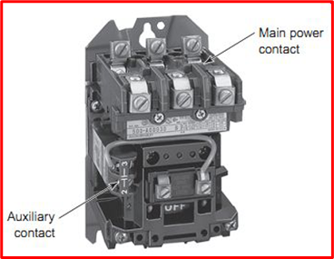
Contactors
Contactors vs relays: A contactor is an electrical device used to turn on or off electrical circuits. It is regarded as a unique variety of relays. The contactor is typically used in applications that require a larger current-carrying capability.
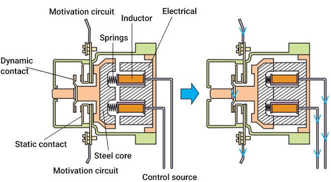
Major Components of a Contactor
The following three components are the major components of a contactor:
- Coil/ Electromagnet
The coil of the contactor produces the driving power necessary to close the connections. An enclosure safeguards the connections and coil of the electromagnet.
- Enclosure
Contactors have enclosures just like any other application, which offer insulation and safeguard the person handling the contacts. The protective casing is constructed from a variety of materials, including polycarbonate, polyester, Nylon 6, Bakelite, thermosetting polymers, and others. The open-frame contactor typically has an extra enclosure that shields it from inclement weather, explosive threats, dust, and oil.
- Contacts
The contacts are responsible for the current carrying function. A contactor can have contact springs, auxiliary contacts, or power contacts, among other sorts of connections. There is a specific role for each kind of contact.
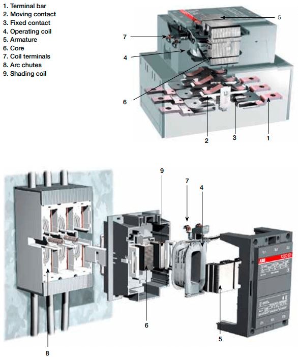
Contactor Diagrams and Symbols
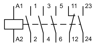
Common electrical diagram symbols used to identify contactors:
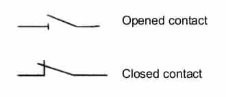

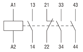
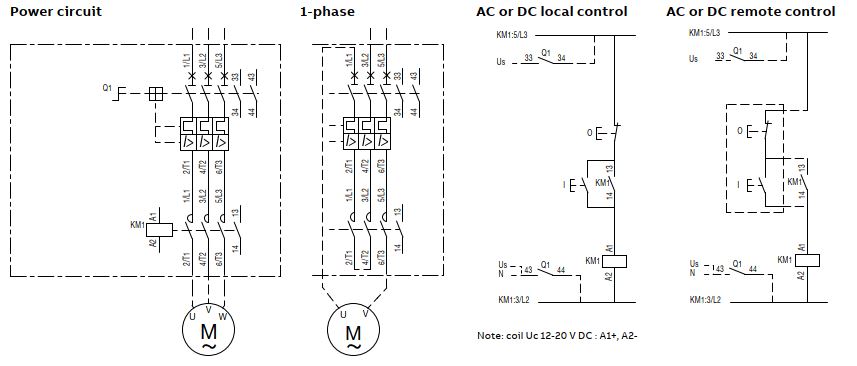
Contactors in a wiring diagram:
Types Of Contactors
The following are the major types of contactors:
- Knife Blade Switch
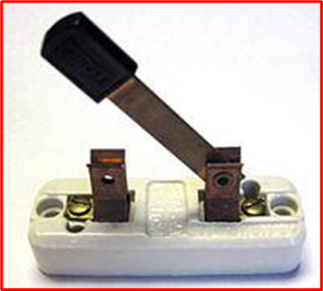
A knife switch is a type of switch used to control the flow of current in a circuit. It consists of hinges that allow levers or metal blades to be lifted from or inserted into slots or jaws. The hinges and bolsters are mounted on an insulated base and the blade has an insulated handle at one end. Current flows through the switch when the blade is pressed against the jaw.
Blade switches can take a variety of forms, including single switches, where the “blade” uses only one slot, and dual switches, where the knife hinge sits between two slots and can use both. In addition, multiple blades can be attached to a single handle and used to activate more than one circuit at a time.
- Double Break Or Manual Contactor
The double break contactor consists of contacts that open at two separate points in the circuit. These break contacts dissipate heat more easily, allowing for longer switch life and allowing the switch to operate at higher voltages.
The double-breaking contacts separate the connections to form two sets of contacts.
The electrical circuit is turned on after the manual control is activated by the operator. Once activated, it transmits power to the load. Double breaks soon replaced knife switches entirely, and variations of this style are still used today.
- Magnetic Contactor
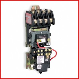
A magnetic contactor is a device that is powered by a magnet. It is used to open and close contacts in motor control circuits and can also be called magnetic switches or contactors.
The control circuit consists of an electromagnetic system and a spring. The current through the coil activates the magnet and the two magnets approach each other. This movement cancels out the two magnetic forces. Therefore, the contacts are closed and the spring energizes the contacts. When the control power is off, the contact breaks.
Magnetic contactors are very widely used devices in most industries. Large commercial industries rely heavily on these devices. They allow them to easily operate heavy loads such as large-capacity motors.
Relays
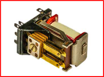
A relay is an electromagnetic switch that can turn on or off a considerably greater electric current and is driven by a relatively small electric current.
Working Principle Of A Relay
Relays come in a variety of sizes, capacities, and applications. Although they could vary in several ways, all relays work in fundamentally the same way: one circuit powers another.
This common way in which a relay works depends on whether the relay is normally open or normally closed.
- Normally Open (NO) Relay
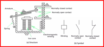
Most relays operate in the open position by default, which means that the second, larger circuit is turned off.
The electromagnet is activated in a normally open relay when power enters the input circuit. By forcing a contact to connect with the second, the larger circuit creates a magnetic field that draws it closed and allows current to flow through. When the power supply is turned off, a spring pulls the contact away from the second circuit, stopping the flow of electricity and shutting off the end device.
- Normally Closed (NC) Relay
An electromagnet moves a physical contact between two points in a normally closed relay in a manner similar to a normally open relay: there are two circuits, the second of which is larger.
The default states are switched around in the case of a NC relay. The contact is drawn away from the second circuit by the magnets when the first circuit is turned on. As a result, NC relays by design maintain the larger circuit in the on position.
Relay Diagrams and Symbols
Common electrical diagram symbols used to identify relays in a circuit:
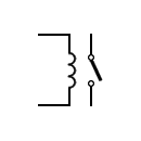
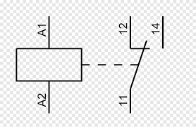
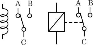
Relays in a wiring diagram or circuit:
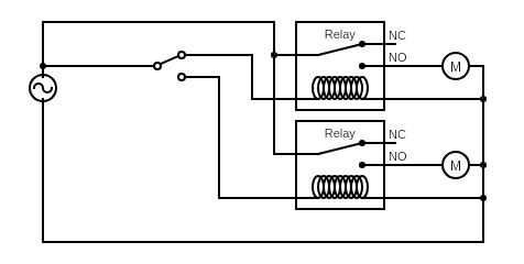
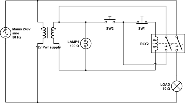
Relay Applications
- The separation of a low-voltage circuit from a high-voltage circuit is achieved using relays.
- Used for managing numerous circuits
- They are also used as automatic switchovers.
- Microprocessors need relays in order to control a large electrical load.
Differences Between Contactors vs Relays
- Relays are typically used to control the contacts of an electrical circuit in response to changes in parameters or conditions in the same circuit or other connected circuits. Contactors, on the other hand, are typically used to make or break connections in a circuit repeatedly under different conditions.
- Relays and contactors usually have different load capacities. Relays are mostly used with electrical loads in the range of about 10 amps or less, while most contactor ratings are greater than 10 amps.
- Relays and contactors are both designed to work both ways, ie. in normally open or normally closed states depending on functional requirements. However, depending on the load requirements and safety needs, take the time to identify whether or not you need one or the other.
(Video) Relays vs Contactors
PDFs & Product Technicals
Explained: General Purpose Relays
Useful Resources
Continued learning:
Brake Rectifiers and Reactors Explained
Brake Choppers: A Detailed Overview
Three Phase Power Explained: What is 3 Phase?
Understanding Step Up and Step Down Transformers
FAQ
What is the purpose of a contactor or relay?
A contactor or relay is an electrical component that is used to switch power circuits on and off. They are used in a variety of applications, from controlling lights and motors to operating complex machinery and equipment.
When can I use a relay instead of a contactor?
Relays are typically used in low power applications, while contactors are used in high power applications. If you need to switch a small amount of current, a relay would be sufficient. However, if you need to switch a large amount of current, you would need to use a contactor.
What is a relay vs solenoid vs contactor?
A relay is an electrical component that switches power circuits on and off using an electromagnetic coil. A solenoid is a device that converts electrical energy into mechanical motion, often used to move a plunger or valve. A contactor is similar to a relay but is designed to switch higher currents and voltages.
Is a contactor a heavy duty relay?
Yes, a contactor is a heavy duty relay designed to switch higher currents and voltages than a standard relay.
Are contactors AC or DC?
Contactors can be designed for either AC or DC applications, depending on the specific requirements of the application. It’s important to choose the correct type of contactor for your application to ensure it can handle the voltage and current requirements.