Brake Chopper: Detailed Overview
The term “braking unit” or “braking chopper” refers to an electrical switch that controls the DC bus voltage by switching the braking energy to a resistor, where it is converted to heat.
By engaging the braking function, it is able to control the DC bus voltage level and prevent overvoltage nuisance tripping by diverting the braking energy to a resistor, where it is radiated as heat.
Working Principle Of A Brake Chopper
A frequency inverter’s DC link voltage is observed using a brake chopper. This monitoring is important because the intermediate circuit is susceptible to power surges. They appear when the motor fails.
The surplus energy in the DC connection is transformed into thermal energy by a component known as the brake resistor, which is coupled to the brake chopper.
The chopper switches the resistance in a manner similar to an electronic switch before the components are put in danger by the DC connection voltage.
The chopper switches the brake resistor off when the intermediate circuit voltage drops and rises to a level higher than the line voltage but lower than the turn-on voltage. As soon as the voltage starts to climb again, the procedure is repeated.
Note: The BRAKING UNIT OR CHOPPER is the controlled path, similar to a switch, that permits regenerative motor energy to flow, and the BRAKE RESISTOR is the component in which this regenerative motor energy will be lost.
Power Dissipation Formula
A Brake Chopper is used to enhance the built-in over-voltage protection found in the majority of modern adjustable speed drives (ASD), which is frequently insufficient to handle a sizable amount of power supplied by the load.
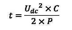
For instance, the formula below can be used to determine how long a given power must be dissipated in a drive to avoid exceeding the withstand rating of the DC bus capacitors:

Where:
Udc = DC bus voltage (above rated)
C = Capacitance (in Farads)
P = Power (in Watts)
For a 460V drive, the recommended DC bus voltage is 460Vac x 1.35 = 621Vdc, and the capacitance is quite small, around 5 millifarads. The capacitors’ typical withstand value, in this example, 807Vdc is 1.3 times higher than their rated value.
Using the above formula with a nominal load of 90 kW and solving for t, the following result is obtained:

t = 7.4×10^-6 seconds. In order to safeguard the DC bus caps, drive electronics must respond promptly.
The impact of heat should be clear from the foregoing as one of the limitations of the brake chopper circuit. The size of the resistors needed to dissipate this energy must take into account both the duty cycle, or the ratio of the amount of time spent conducting to total time, and their current-carrying capability.
Usefulness Of Brake Chopper
- Despite these limitations, a brake chopper is often a less expensive investment than a new regenerative drive.
- Additionally, unless utilized in a safety-restricted mode, the chopper will continue to operate even if the main power source is lost.
- Choppers are needed when braking is only seldom necessary, the amount of braking energy required is not great, or braking is still necessary in the event of a power outage.
Bonus: Regenerative Drives
The regenerative drive is an alternative to the conventional braking circuit. This component transmits motor regeneration energy back to the line and serves as the variable frequency drive (VFD) power source.
Since a brake resistor does not produce heat, the recovered energy can be used to power other electrical loads in the building, and the machine requires less energy to cool because it uses less energy overall. Large energy cost savings may result from this.
Bonus: Integrated Brake Transistor

There are some applications that call for effective and reliable brakes. A potential inbuilt transistor with a 100% duty cycle rating is required. Most VFD manufacturers offer a separate braking module which does not include the braking transistor in their drives. As a result, more room will be needed, which will cost more money.
While the brake transistor duty rating of some manufacturers is not up to 100%, it is advisable to use a bigger drive or braking module to handle the braking current.
The size and requirements of the brake resistor(s) must also be taken into consideration when establishing a braking circuit. They must be the proper size to prevent harm. The braking circuit may be harmed if the resistance is too low and the braking transistor’s rated maximum brake current is exceeded and if the excess voltage is not sufficiently dissipated over-voltage will develop.
Useful Resources
Continued learning:
Three Phase Power Explained: What is 3 Phase?
Understanding Step Up and Step Down Transformers
Fault Interrupters: AFCI vs GFCI


