Three Phase Induction Motors
Three phase motors are a type of AC motor that operates using the principle of electromagnetic induction. They differ from single-phase AC motors in that they use three-phase power, which provides smoother torque and higher efficiency. For a thorough understanding of three-phase induction motors, one must first possess a solid foundation in basic electrical knowledge.
They are among the most widely used electric motors in industrial applications, due to their simple and robust design, high efficiency, and relatively low cost.
Working Principle of Three Phase Induction Motors
A three phase induction motor relies on a rotating magnetic field created by the three-phase power supply. This magnetic field induces a current in the rotor windings, which generates its own magnetic field. The interaction between the rotor and stator magnetic fields produces torque, causing the rotor to rotate.
Rotating Magnetic Field
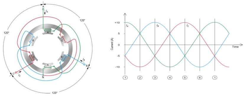
A rotating magnetic field is produced by the combination of sinusoidal currents in each of the stator windings, with a phase difference of 120° between each winding. The resulting magnetic field rotates around the motor at a synchronous speed (Ns), which is calculated using the formula:
Ns = (120 * f) / P
Where Ns is the synchronous speed in revolutions per minute (RPM), f is the frequency of the supply in hertz (Hz), and P is the number of poles in the motor.

Process in Key Steps:
Step 1: Stator Winding Excitation
When a three-phase power supply is connected to the stator windings, each winding generates a magnetic field. These magnetic fields are sinusoidal in nature and have a phase difference of 120° between each winding. This results in a rotating magnetic field within the stator.
Step 2: Induction of Current in the Rotor
As the rotating magnetic field from the stator passes over the rotor bars, an electromotive force (EMF) is induced in the rotor, according to Faraday’s law of electromagnetic induction. This induced EMF generates currents in the rotor bars, which in turn create their own magnetic field.
Step 3: Interaction Between Stator and Rotor Magnetic Fields
The rotor’s magnetic field interacts with the stator’s rotating magnetic field, creating a torque that causes the rotor to rotate. The direction of the torque depends on the relative direction of the magnetic fields. In a three-phase induction motor, the rotor always tries to follow the rotating magnetic field of the stator.
Step 4: Rotor Slip
In practice, the rotor never reaches the same speed as the stator’s rotating magnetic field (synchronous speed). The difference in speed is known as “slip,” and it is essential for the induction motor to develop torque. If the rotor were to reach synchronous speed, there would be no relative motion between the stator’s rotating magnetic field and the rotor, resulting in zero induced EMF and torque.
The slip (s) is defined as the ratio of the difference between the synchronous speed (Ns) and the rotor speed (Nr) to the synchronous speed:
slip (s) = (Ns – Nr) / Ns
Step 5: Torque-Speed Characteristics
The torque developed by the induction motor is influenced by the slip and the motor’s characteristics. As the slip increases, the torque increases up to a certain point, known as the “maximum torque” or “pull-out torque.” Beyond this point, the torque decreases, and if the slip becomes too high, the motor may stall.
Note: Three-phase induction motors can also be integrated into a motor starter system for better control and protection.
Did you know?
Digital phase converters allow three-phase induction motors to operate using a single-phase power supply. They are particularly useful for applications where a three-phase power supply is unavailable or impractical. They use advanced microprocessor-based control circuits to generate the missing phases, ensuring a balanced and stable three-phase output.
Construction of Three Phase Induction Motors
A three-phase induction motor consists of two main parts: the stator and the rotor.
Stator
The stator is the stationary part of the motor, which houses the three phase windings. These windings are arranged in slots around the inner circumference of the stator core, which is typically made of laminated iron to reduce eddy current losses.
Elements:
- Stator Core: The stator core is made of laminated iron or steel, which helps to minimize eddy current losses and hysteresis. The core is constructed by stacking thin sheets of electrical steel, insulated from each other by a varnish coating. The laminations improve the motor’s efficiency by reducing energy losses due to the alternating magnetic field.
- Stator Windings: The stator windings are the copper wire coils that are wound around the stator core. These windings are placed in slots within the core, typically following a distributed winding pattern, which ensures a more uniform magnetic field distribution. The windings are connected to the three-phase power supply and are responsible for creating the rotating magnetic field.
- Stator Frame: The stator frame is the external housing that supports and protects the stator core and windings. It is typically made of cast iron, steel, or aluminum and helps dissipate heat generated during motor operation.
Rotor
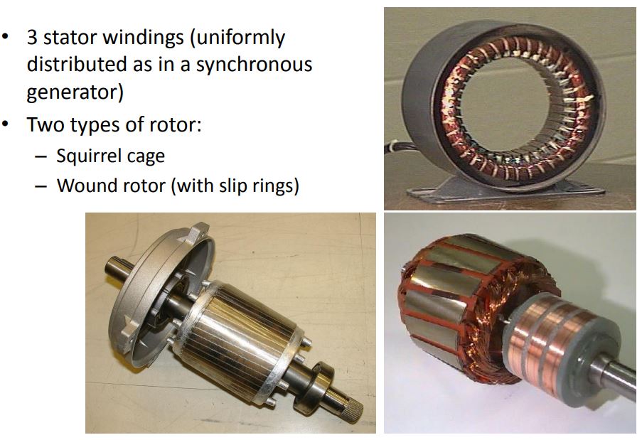
The rotor is the rotating part of the motor, which consists of conductive bars that are shorted at each end by end rings. The rotor can be either a squirrel cage rotor, which is the most common type, or a wound rotor. A squirrel cage rotor has simple construction and requires no maintenance, while a wound rotor has windings similar to the stator and requires slip rings and brushes for operation.
Elements:
- Rotor Core: The rotor core is also made of laminated iron or steel, similar to the stator core. The core contains conductive bars that are shorted at each end by end rings, forming a “squirrel cage” structure in the case of squirrel cage rotors.
- Rotor Windings (Wound Rotor) or Bars (Squirrel Cage Rotor): In a squirrel cage rotor, the conductive bars are embedded in the rotor core’s slots and shorted by the end rings. This simple construction requires no external connections and has low maintenance requirements. In a wound rotor, the rotor windings are similar to the stator windings and are connected to external circuits through slip rings and brushes. This allows for better starting torque and speed control but comes with higher maintenance requirements.
- Shaft: The rotor is mounted on a shaft, which is supported by bearings that allow it to rotate smoothly. The shaft is typically made of steel and transmits the torque generated by the motor to the load.
PDF / Technicals
Induction Motors (PDF)
Models (PDF)
Types of Three Phase Induction Motors
There are two main types of three-phase induction motors, classified based on the type of rotor used:
- Squirrel Cage Induction Motor:
These motors use a squirrel cage rotor, which consists of conductive bars shorted by end rings. They are robust, low-cost, and require little to no maintenance. - Wound Rotor Induction Motor:
These motors use a wound rotor, which consists of windings similar to the stator. They require slip rings and brushes for operation, allowing for better starting torque and speed control. However, they have higher maintenance requirements and costs compared to squirrel cage induction motors.

Squirrel Cage Induction Motor
Squirrel cage induction motors, also known as cage rotor induction motors, are the most common type of three-phase induction motors. They are characterized by their simple, robust construction, low cost, and low maintenance requirements.
- Rotor Construction: The rotor in a squirrel cage induction motor consists of conductive bars embedded in the rotor core’s slots. These bars are shorted by end rings at both ends, creating a structure that resembles a squirrel cage. This design provides a shorted, low-resistance path for the induced current, resulting in high efficiency and robust performance.
- Starting Method: Squirrel cage induction motors have a high starting current, typically 5 to 8 times the rated full-load current. This high current can cause stress on the power supply and the motor itself. Various starting methods, such as direct-on-line (DOL) starters, star-delta starters, and soft starters, can be employed to reduce the starting current and ensure smooth motor operation.
- Speed Control: Speed control in squirrel cage induction motors is generally more challenging compared to wound rotor motors. Voltage and frequency control methods, such as variable frequency drives (VFDs), can be used to control the motor’s speed effectively.
Wound Rotor Induction Motor
Wound rotor induction motors, also known as slip ring induction motors, are less common than squirrel cage induction motors. They offer better starting torque and speed control but come with higher maintenance requirements and costs.
- Rotor Construction: The rotor in a wound rotor induction motor consists of windings similar to those in the stator. These windings are connected to external circuits through slip rings and brushes, which enable the rotor to rotate while maintaining electrical contact with the stator.
- Starting Method: Wound rotor induction motors have lower starting currents compared to squirrel cage motors due to the presence of external rotor resistance. By varying the external rotor resistance during startup, the starting torque can be increased, and the starting current can be controlled more effectively.
- Speed Control: Speed control in wound rotor induction motors is more straightforward than in squirrel cage motors. By adjusting the external rotor resistance, the slip and torque characteristics can be modified, allowing for smooth and precise speed control.
(Video) Technical Animation
FAQ
What are the 3 types of 3-phase motors?
There are several types of 3-phase motors, but the three most common types include: Squirrel Cage Induction Motors, Wound Rotor Induction Motors, and Synchronous Motors
Is induction motor and 3-phase induction motor the same?
The term “induction motor” can refer to both single-phase and three-phase induction motors. However, when people use the term “induction motor” without specifying the number of phases, they are typically referring to a three-phase induction motor, as it is the most widely used type of induction motor in industrial applications.
Why is it called 3-phase induction motor?
It is called a 3-phase induction motor because it operates on three-phase alternating current (AC) power, and the torque is generated through the principle of electromagnetic induction. In a 3-phase induction motor, the stator windings are energized by a three-phase power supply, creating a rotating magnetic field that induces currents in the rotor, generating torque and causing the rotor to rotate.
What are the advantages of 3-phase induction motors?
Some advantages of 3-phase induction motors include: High efficiency and power factors, simple and robust construction, self-starting capabilities, high starting torque, wide availability, and the capability to handle heavy loads.
Additional Resources
For further information on related topics, consider exploring the following resources: