Transformers: Detailed Overview
A transformer is an electrical device that transfers energy from one electric circuit to another using the electromagnetic induction principle.
It is intended to change the AC voltage between the circuits while keeping the current’s frequency constant. In this article, We take a close look at how transformers do this as well as the key differences between step up and step down transformers.
Important note to remember: Transformers accomplish this without establishing a conductive link between the two circuits.
This is made feasible by using Faraday’s Law of Induction, which explains how an electric circuit interacts with a magnetic field to produce an electromotive force (EMF).

Types Of Transformers
Transformers can be grouped majorly into three based on their voltage level. They are:
- Step down Transformer
- Step up Transformer
- Isolation Transformer
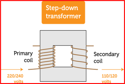
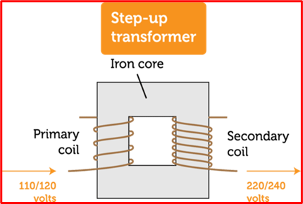
Step-down transformers provide a lowered voltage applied to the primary coil at the secondary coil, whilst step-up transformers provide an increased voltage applied to the primary coil at the secondary coil. We take a closer look at how step up and step down transformers work below.
Transformers used primarily to isolate electrical circuits are called isolation transformers because they provide the same voltage applied to the primary at the secondary.
Step Up Versus Step Down Transformers

A step-down transformer lowers the voltages across the secondary output from the primary voltage level. This is accomplished by the primary-to-secondary winding ratio.
For step-down transformers, the primary side has more windings than the secondary side. As a result, the ratio of primary to secondary windings remains greater than 1.

A step-up transformer is exactly the opposite of a step-down transformer. The low primary voltage of a step-up transformer is raised to a high secondary voltage.
Once more, the primary-to-secondary winding ratio is what makes it happen.
The ratio between the primary winding and secondary winding for the step-up transformer is below 1. This simply means the secondary winding has more turns than the primary winding.
The key differences between step up and step down transformers are highlighted below:
- The key difference between step-up and step-down transformers is that the step-up transformer increases the output voltage whereas the step-down transformer decreases the output voltage.
- The low-voltage winding serves as the primary coil and the high-voltage winding serves as the secondary coil in a step-up transformer. The low voltage winding is the secondary coil in a step-down transformer, in contrast.
- In the step-up transformer, the number of turns in the primary winding is less than the secondary winding while in the step-down transformer, the number of turns in the primary winding is more than the secondary winding.
- A Step-up transformer is generally used for power transmission while a step-down transformer is used in power distribution.
- The step-down transformer lowers voltage from 440 volts to 220 volts, 220 volts to 110 volts, or 110 volts to 24 volts, 20 volts, or 10 volts, while the step-up transformer increases the voltage from 220 volts to 11,000 volts or more.
Working Principle Of A Transformer
A transformer consists of two sets of windings namely: the primary winding which collects power and the secondary winding which provides power.

On a magnetic iron circuit core, the primary and secondary windings are twisted together, but they are not in direct touch with one another. To minimize core loss, the core is formed of a soft magnetic substance composed of laminates joined together. The energy loss within the core brought on by an alternating magnetic flux is known as core loss. The functioning of the core material is finally destroyed by an unstable magnetic field.
Current passes through the coil and induces a magnetic field when the primary winding is linked to a power source. A portion of this magnetic field forms a mutual induction connection with the secondary windings, causing a current to flow and a voltage to be generated at the secondary (load) side.
The number of turns in the secondary winding in relation to the primary winding determines the voltage generated at the load side.
This is how the voltage is transformed
Np/Ns = Vp/Vs = N
Where,
N = turns ratio
Np = Number of turns in the primary coil
Ns = Number of turns in the secondary coil
Vp = Voltage applied to the primary
Vs = Voltage at the secondary
Regardless of the kind of transformer, all transformers have some characteristics in common:
- Input and output power frequencies are the same.
- Every transformer uses the principles of electromagnetic induction.
- There is no electrical connection between the primary and secondary coils (except for autotransformers).
- There are no friction or windage losses, unlike with conventional electrical devices, because there are no moving elements needed to transfer energy.
Useful Resources
Transformers For the Electrician
Transformer Theory, Design and Applications
Electrical Transformer and Rotating Machines
FAQs
How do capacitors work?
Capacitors are used to store electricity. In contrast to the usefulness of resistors, capacitors do not dissipate energy in their optimal form. Read more..
What is alternating current?
Alternating current (AC) is an electric current that reverses direction periodically. This means that the voltage of an AC signal also reverses direction periodically.
The frequency of an AC signal is the number of times per second that the current or voltage reverses direction. Read more..
What is Ohm’s Law?
Ohm’s law states that the current through a conductor between two points is directly proportional to the potential difference across the two points. In other words, the higher the voltage, the higher the current. Read more..