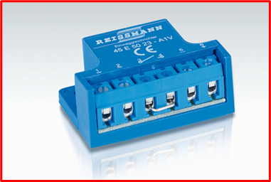
Brake Control Rectifier / Reactor
Brake rectifiers or “Brake control rectifiers” convert AC voltage to DC voltage.
Rectifiers are employed because most applications need AC energy to run the motor, but need DC power to control the brakes, which is rarely available.
They can often be found in the terminal box, or “pecker head” usually located on the motor itself.
Features and Functions

A rectifier consists of the following:
- A separate power source for every brake
- Small size; installed inside the terminal box.
- The availability of various types, voltage options, and release/engagement modes.
- Capable of mounting in a different control cabinet.
- Integrated voltage spike protection
By Manufacturer:
(PDF) Nord Brake Rectifier, GHE40L (nord.com)
(PDF) Lenze Brake Rectifier Technical (lenze-selection.com)
(PDF) SEW Brakes Product Bulletin
Types Of Rectifiers
Full Wave Rectifier
This is the rectifier that produces a unidirectional DC supply to the load or the brake by rectifying both the positive and negative half-cycles of the AC input signal. The output voltage (VDC = 0.90 x VAC) is 90% of the input voltage.
Half-Wave Rectifier
This is the rectifier that exclusively converts the AC input signal’s alternate half-cycles into a unidirectional DC source for the load or the brake. The output voltage (VDC = 0.45 x VAC) is 45% of the input voltage.
Dual-Wave Rectifier
Depending on how it is coupled to the AC input signal, a rectifier can be configured as either a full-wave or half-wave rectifier.
Push-hybrid Or Fast Action Rectifiers
An initial “push” is provided by a push-hybrid rectifier, also known as a fast-acting brake rectifier, in the form of a timed full-wave brake-release function. This process is subsequently followed by a continuous half-wave brake-holding function. There are two methods for applying these rectifiers as follows:
- “Overexcitation” of the brake coil provides faster brake release or improved cycling capacity. The DC voltage of the brake coil is determined based on using a half-wave rectifier. The output voltage is 45% of the input voltage (VDC = 0.45 x VAC).
- “Reducer-Power Holding” of the brake coil maintains the brake in a released state by using only 25% of the power needed for the initial brake release. This results in very fast brake stopping. The DC voltage of the brake coil is determined based on using a full-wave rectifier. The output voltage is 90% of the input voltage (VDC = 0.90 x VAC).
General Principles For Electrical Braking
The mechanics are used to assess the need for braking. The mechanical system must typically be braked within a predetermined time limit, or there are portions of the operation where the motor on the generator side runs at a constant or slightly variable speed.
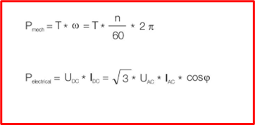
It is significant to remember that electrical brake devices are sized for certain braking powers. The formula for braking torque and speed determines the mechanical braking power. The power increases with increasing speed. A certain voltage and current are then used to convey this electricity. For the same power formula, a higher voltage results in a lower current requirement. In low-voltage AC drives, the cost is primarily determined by the current.
In the formula, we see the term cosϕ. This term defines how much motor current is used for magnetizing the motor. The magnetizing current does not create any torque and is therefore ignored.
On the other hand, this motor magnetizing current is not taken from the AC supply feeding the converter, ie, the current to the inverter is lower than the current fed to the motor. This fact means that on the supplying side the cosϕ is typically near 1.0. Note that in the formula, it has been assumed that no loss occurs when DC power is converted to AC power. There are some losses in the conversion, but in this context, the losses can be ignored.

Where:
T: Torque (Newton meter, Nm)
cosϕ: Cosine of electrical angle between the fundamental voltage and current
n: Rotation speed [revolutions per minute, rpm]
Uac: Alternating Current Voltage [volts]
Idc: Direct Current [Amperes]
General Safety
Only qualified personnel should attempt the installation, operation, and maintenance of brakes and brake rectifiers. If you have a question about a procedure or are uncertain about any detail, seek clarification and DO NOT PROCEED.
Dangers Associated With Brakes And Brakes Rectifiers
- High electrical voltage is present in this equipment
Before performing any maintenance on the brake, disconnect, and lock out all power to the electric motor and brake.
- Compliance with all local, state, and federal electrical and safety codes is the user’s responsibility. Wiring procedures, appropriate grounding, disconnects, and over-current protection are very crucial.
- When performing brake maintenance, make sure the load is supported. The load will be released if the brake is turned off or the brake is removed from the motor, which could result in serious damage or even death.
- Serious physical harm or death could result from failing to take the proper precautions and following the right procedures.
Recommended Tools
Useful Resources
Continued Learning:
Brake Choppers: A Detailed Overview
Three Phase Power Explained: What is 3 Phase?
Understanding Step Up and Step Down Transformers
(Video) Testing Brakes
FAQ
How do you test a motor brake rectifier?
To test a motor brake rectifier, you can use a multimeter to check the resistance of the diodes in the rectifier. Place the multimeter in diode mode and touch the test leads to the diodes. If the diode is working properly, the multimeter should read a low resistance in one direction and a high resistance in the other direction.
What is the purpose of a brake rectifier?
A brake rectifier is used in a motor control circuit to provide a DC voltage to the brake coil when the motor is stopped. The brake rectifier helps to slow down and stop the motor quickly, reducing wear and tear on the mechanical components of the motor.
Does a rectifier change voltage?
A rectifier does not change the voltage of the input signal. It simply converts an AC voltage to a DC voltage by allowing current to flow in one direction only. The output voltage of a rectifier will be the same as the peak value of the AC input voltage.
What is a half-wave rectifier for motor brake?
A half-wave rectifier is a type of rectifier that only allows current to flow in one direction for half of the AC cycle. In a motor brake circuit, a half-wave rectifier can be used to provide DC voltage to the brake coil. However, a half-wave rectifier is less efficient than a full-wave rectifier and may result in a slower response time for the brake.