Intro to Rectifiers and Diodes
The key to troubleshooting rectifiers is to understand what a rectifier is and how it works.
A rectifier is an electrical device that converts alternating current (AC), which periodically reverses direction, to direct current (DC), which flows in only one direction. The process is known as rectification.
A diode is a two-terminal electronic component that conducts current primarily in one direction (asymmetric conductance); it has low (ideally zero) resistance to the flow of current in one direction, and high (ideally infinite) resistance in the other.
How Do Rectifiers Work?
In order to understand how rectifiers work, it is necessary to understand the basics of electricity:
- Electricity is the flow of electrons through a conductor, such as a wire. In order for this flow to occur, there must be a difference in electric potential between the two ends of the conductor
- This potential difference is measured in volts, and it determines the amount of current that will flow through the conductor.
- The current is measured in amperes, and it is determined by the resistance of the conductor.
Rectifiers are devices that are used to change alternating current (AC) into direct current (DC).
Rectifiers work by allowing only half of the AC cycle to pass through them. During the positive half-cycle, the rectifier allows electrons to flow from the negative terminal to the positive terminal. During the negative half-cycle, the rectifier blocks the flow of electrons.
As a result, DC (direct current) is produced.
Is a Diode a Rectifier?
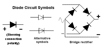
Diodes are semiconductor devices that allow current to flow in only one direction, making them useful for a variety of applications such as rectification, voltage regulation, and signal modulation. The term “rectifier” refers to the diode’s ability to convert alternating current (AC) into direct current (DC).

Learn more about this in: Diodes Explained: Diode Polarity and Circuits
Understanding Thermal Voltage
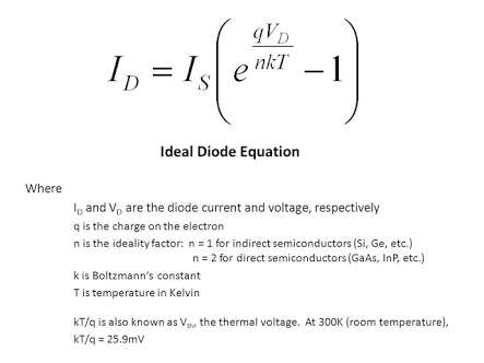
When discussing diodes and rectifiers, it is important to understand the concept of thermal voltage.
What is thermal voltage?
The thermal voltage of a semiconductor material is the voltage that must be applied across the material in order to produce a current of one ampere per square centimeter of cross-sectional area.
This value is determined by the material’s band gap energy, which is the amount of energy required to move an electron from the valence band to the conduction band.

- In silicon, the band gap energy is 1.1 electron volts, so the thermal voltage is approximately 5.5 volts.
- For germanium, the band gap energy is 0.67 electron volts, so the thermal voltage is approximately 3.3 volts.
- When used in diodes and rectifiers, these materials can handle voltages that are several times their thermal voltage without damage.
- As a result, they are well suited for use in electronic devices.
Types of Rectifiers
Full Wave and Half Wave Rectifiers
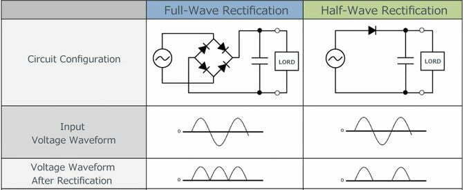
Full-wave rectifiers utilize both the positive and negative cycles of the AC wave, whereas half-wave rectifiers only utilize one cycle. As a result, full-wave rectifiers are more efficient than half-wave rectifiers. However, full-wave rectifiers require more components and are more expensive to construct.

For this reason, half-wave rectifiers are typically used in low-power applications.
Bridge Rectifiers
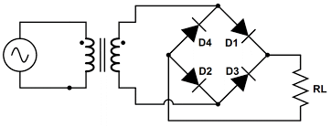
A diode bridge is an arrangement of four diodes in a bridge circuit configuration that provides the same polarity of output voltage for either polarity of input voltage.
When used in its most common application, for conversion of an alternating polarized input voltage into a direct polarized output voltage, it is known as a bridge rectifier.

Bridge rectifiers have higher efficiency than standard rectifier diodes due to their increased surface area, but they are also more expensive and tend to generate more heat.
Useful Resources
DC Power Circuit: Direct Current Explained
What Is AC Power: Alternating Current
Fundamentals of Power Electronics
FAQ
What is an arc fault circuit interrupter (AFCI)?
An AFCI is a type of circuit breaker that is designed to protect against electrical fires caused by arcing faults. Read more..
What is alternating current?
Alternating current (AC) is an electric current that reverses direction periodically. This means that the voltage of an AC signal also reverses direction periodically.
The frequency of an AC signal is the number of times per second that the current or voltage reverses direction. Read more..
What is a rectifier?
A rectifier is an electrical device that converts alternating current (AC), which periodically reverses direction, to direct current (DC), which flows in only one direction. The process is known as rectification. Read more..