Identifying Motors In A Circuit
While the specific design of a motor will vary depending on its intended use, there are some general characteristics that can help you identify a motor in a circuit.
Before we begin, it’s important to understand basic motor components and how they work. For example, motors typically have two sets of coils, called stator coils and rotor coils. The stator coils are stationary and provide a magnetic field that the rotating rotor coil interacts with to create motion.
In addition, motors typically have a commutator, which helps to reverse the current in the rotor coils and keep the motor running smoothly.
By understanding these basic components, you can start to identify a motor in any circuit.
Reading Electrical Wiring Diagrams
Electrical wiring diagrams show the connections between the wires in an electrical circuit. They can be either simple or complex, depending on the number of devices in the circuit and the level of detail required. However, all electrical wiring diagrams share some basic symbols and conventions.
The most important elements of an electrical wiring diagram are the lines that represent the wires. These lines can be either straight or curved, but they must always connect at junctions known as nodes.
In addition, electrical wiring diagrams often use standard symbols to represent different types of components, such as resistors, capacitors, and inductors.
By understanding the basic conventions of electrical wiring diagrams, it is possible to decipher even the most complex circuits.
PDFs / Technicals
Motor Control Circuits (PDF)
Motors: Electrical Circuits and Line Diagrams (PDF)
AC Motor Symbol

This symbol represents an AC motor
Dual Speed Motor Symbol

This symbol represents a dual speed motor
Generic Motor Symbol
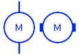
These symbols are generic representations of a motor
DC Motor Symbol
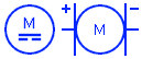
These symbols represent DC motors
Simple DC Motor Circuit
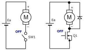
These represent basic DC motors in a wiring diagram
Simple AC Motor Circuit
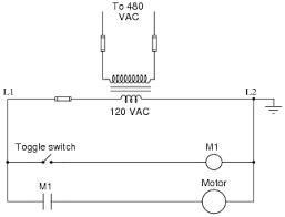
Simple AC motor circuit in a wiring diagram
Forward Reverse Motor Control Diagram
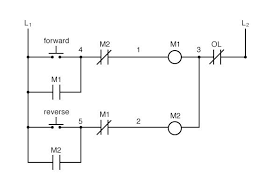
A simple forward reverse motor control diagram
Simple 3-Phase Motor Circuit
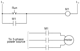
Basic 3-phase motor circuit in a wiring diagram
FAQs
Popular: AC Motors: How Do They Work?
How to use Ohm’s Law?
Ohm’s law is used in many branches of physics, including electricity, magnetism, and optics. It can be used to design electrical circuits, calculate power dissipation in electronic devices, and troubleshoot electrical problems. Read more.
What is a synchronous motor?
Unlike an asynchronous AC motor, a synchronous AC motor rotates at the same speed as the frequency of the AC power supply. In order to achieve this, the synchronous AC motor must be synchronized with the power supply using a feedback system. Read more..
How does and AC motor work?
An AC motor works by using electromagnetism to convert electrical energy into mechanical energy. The alternating current creates a rotating magnetic field that interacts with the armature, or rotor, of the motor to create torque. Read more..